IMPORTANT – DO NOT ATTEMPT THIS MODIFICATION UNLESS YOU ARE CERTAIN YOU HAVE THE SKILLS AND EQUIPMENT REQUIRED, YOU COULD DAMAGE YOUR AMPLIFIER. THIS MODIFICATION IS NOT ENDORSED BY ACOM. NO RESPONSIBILITY IS TAKEN BY M0YOM, ACOM OR ANYONE ELSE FOR ANY DAMAGE OR INJURY THAT MAY RESULT FROM PERFORMING THIS MODIFICATION. PERFORMING THIS MODIFICATION WILL LIKELY VOID YOUR WARRANTY.
Why carry out this modification?
When the ACOM 600S and ACOM 1200S were designed, the designers chose to support a regular straight through RS-232 cable for computer control, this differed from the Null Modem cable that was required by the ACOM 2000A. However, a mistake was made in the design and for the remote power on operation to function the DTR, DSR, RTS & CTS lines still require wiring as though they were a Null Modem cable. This means that for full computer control and remote power on operation to be possible, a custom cable must be used. This modification enables the use of a completely standard straight through RS-232 cable for both computer control and remote power on. If you never use the remote power on capabilities of the ACOM 600S then this modification is not required and should not be attempted.
Once this modification is complete a standard straight through RS-232 cable can be used however the ACOM 600S will still support a custom wired cable if one does get connected in the future, allowing for the wiring noted in the manual to be utilised should someone who is not aware the modification has been made uses the amp in the future.
What about the ACOM 1200S?
The ACOM 1200S appears to suffer from the same unusual wiring of the RS-232 port and thanks to Tyler K7TDM this modification has now been confirmed to work on the ACOM 1200S. The amplifier disassembly is different to the ACOM 600S however the modification to the RS-232 port is identical.
It is my suspicion that all solid state ACOM Amplifiers suffer from this non-standard pinout issue on the RS-232 port which would lead me to suspect that it may have been a deliberate design choice, although for what reason I’m not sure.
What will you need
- A medium Phillips (cross head) screwdriver
- A short stubby Phillips (cross head) screwdriver
- Small pair of pliers or 5mm Hex Socket
- A good soldering iron with a small tip
- Some solder
- Some small guage equipment wire (30AWG Kynar wire is perfect)
- 60-90 minutes of time
- A desoldering tool or station would be useful but isn’t neccesary if you’ve got a small enough iron
Before you start
Disconnect all wires from the ACOM 600S and unplug it from the mains (DO NOT WORK ON LIVE EQUIPMENT), I would suggest leaving it for 30 minutes or so to allow any charge left in any capacitors to fully drain just to be on the safe side.
Step 1 – Remove Cover
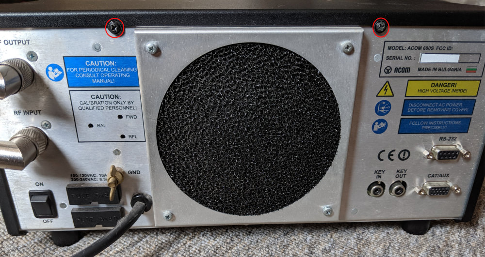
Begin by removing the two screws located at the rear of the amp (circled in red)
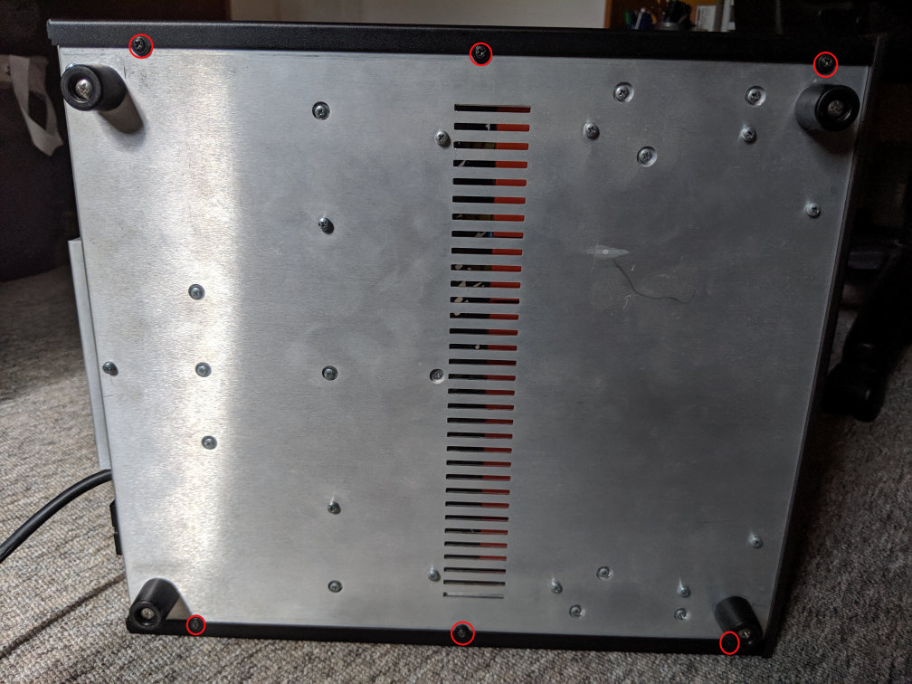
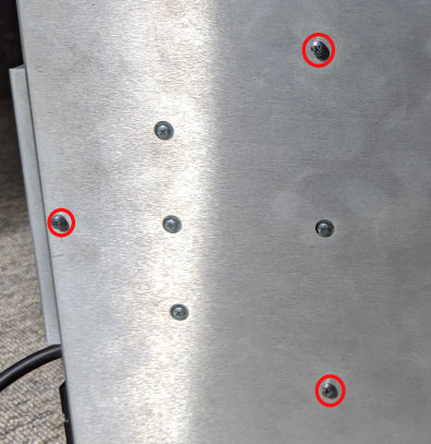
Then remove the six screws on the bottom of the amp (circled in red)
Finally remove the eight screws on the top of the case (circled in red)
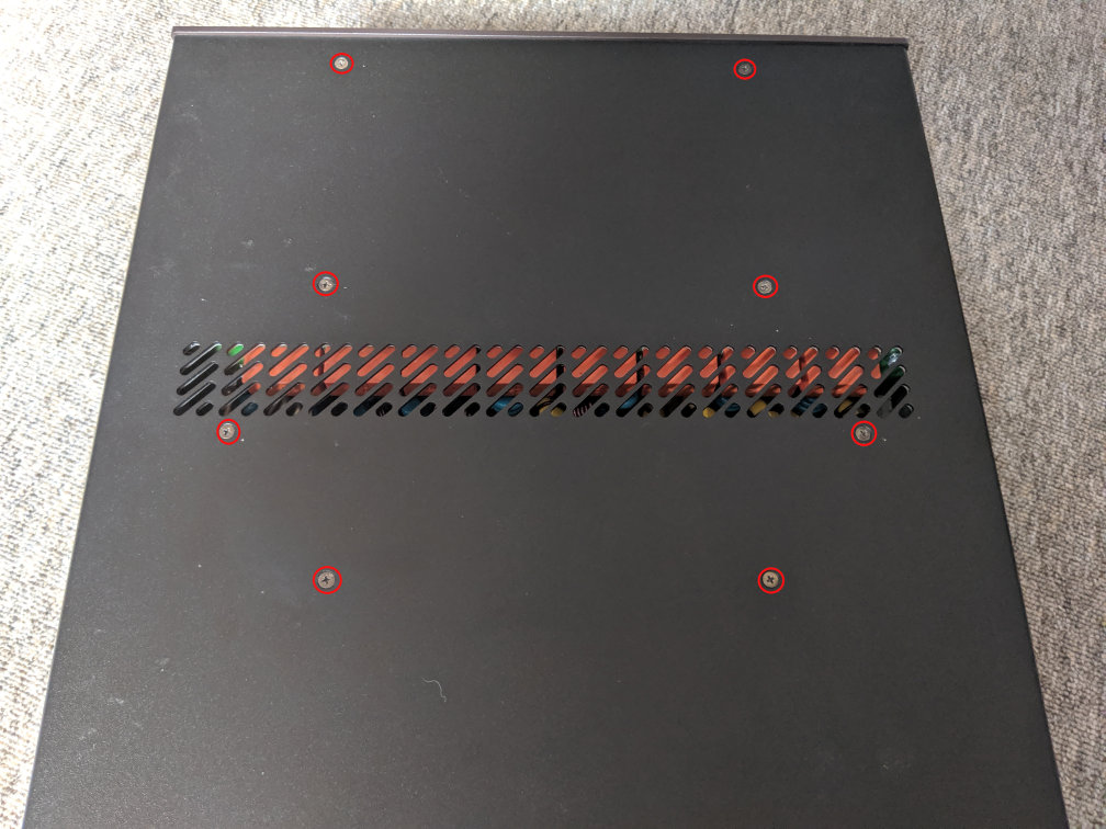
The outer case should then easily slide towards the rear of the amp and can be removed.
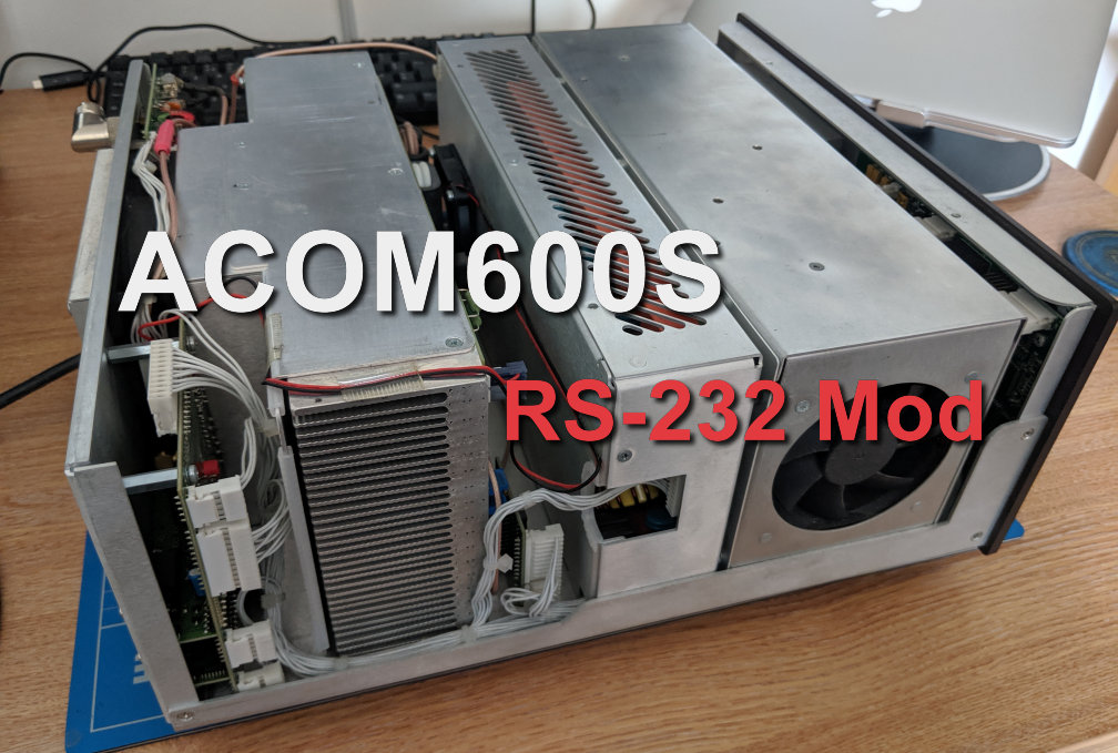
The board we’re interested in is the CPU Board which has the RS-232 board and port attached to it.
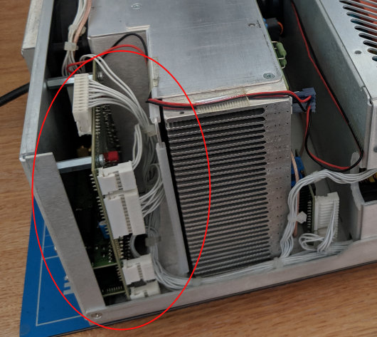
Unfortunatley we can’t get to the screws that hold it in as the large rear module is blocking access so we must first remove the rear module.
Step 2 – Remove Rear Module
Removing the rear module can be a little tricky so be patient and take your time.
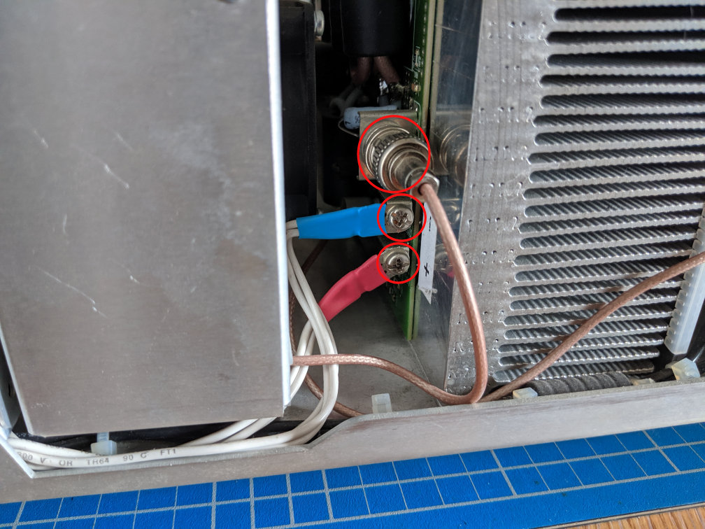
Begin by disconnecting the BNC connector and the Positive and Negative terminals
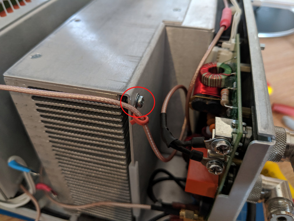
Next, remove the small retaining clip that holds the coax cable
The rear module is held in place by 3 screws on the bottom of the case, these should now be removed
Finally, remove the fan connector, this is the lower of the two connectors leading to the fan
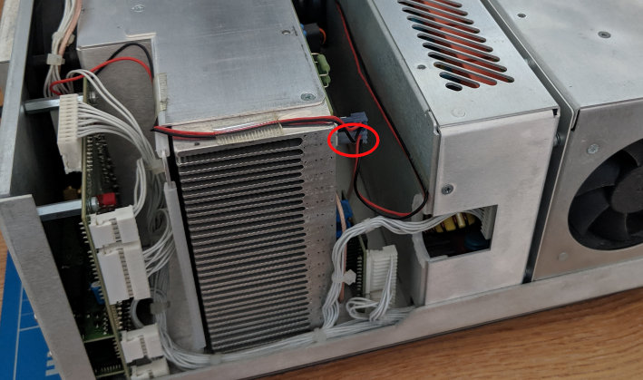
It should now be possible to lift the module out of the amp and set it to the side, it will still be connected and can be a little tricky to maneuver past the wiring, take your time.
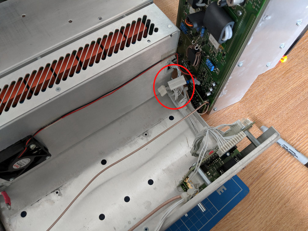
You may have to also disconnect the two white connectors shown below, however this isn’t strictly neccesary.
Step 3 – Remove CPU Board
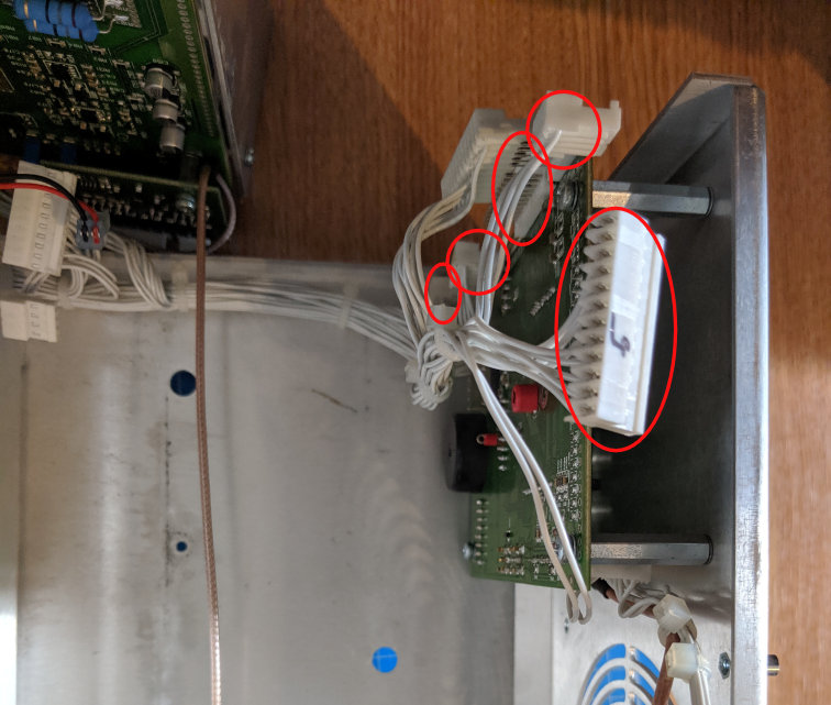
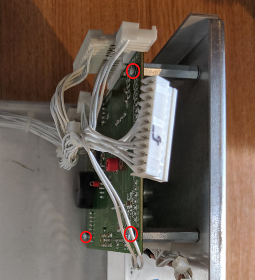
We’re now ready to start removing the CPU Board. Begin by disconnecting the 5 white connectors
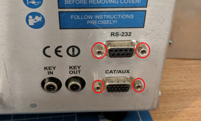
Now remove the 4 retaining bolts from the RS-232 and CAT/AUX ports on the back of the amp
You can now remove the 3 screws holding the CPU Board to the case
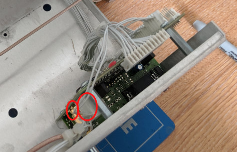
Finally remove the two white connectors and the SMA Connector from the rear side of the CPU board. Make note of which SMA connector is used as there is a second un-connected one on the board.
The CPU board should now be seperated from the amp and can be worked on seperatly.
Step 4 – Wiring Modification
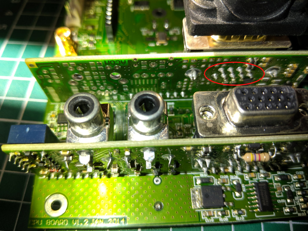
The CPU board has two smaller daughter boards connected to it, one for the CAT/AUX connector and the other for the RS-232 port, we are interested in the RS-232 daughter board. These are soldered in place and cannot easily be seperated. We’ll be needing to wire some jumpers onto the back of the RS-232 port, you may find it easier to do this with the daughter board still connected, however I chose to remove it from the CPU board as I needed to verify pinouts. If I was doing this again I would certainly leave it connected to the CPU board.
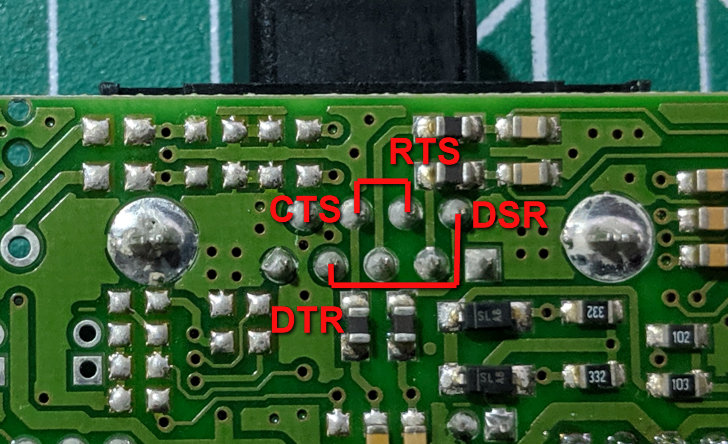
The board pinouts are as follows
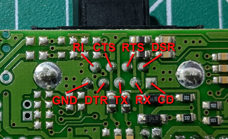
You’ll notice that the DTR and RTS pins have no traces attached to them (i’ve verified this with a meter). We need to connect the RTS pin to the CTS pin and the DSR pin to the DTR pin.
I made this modification using some fine Kaynar wire
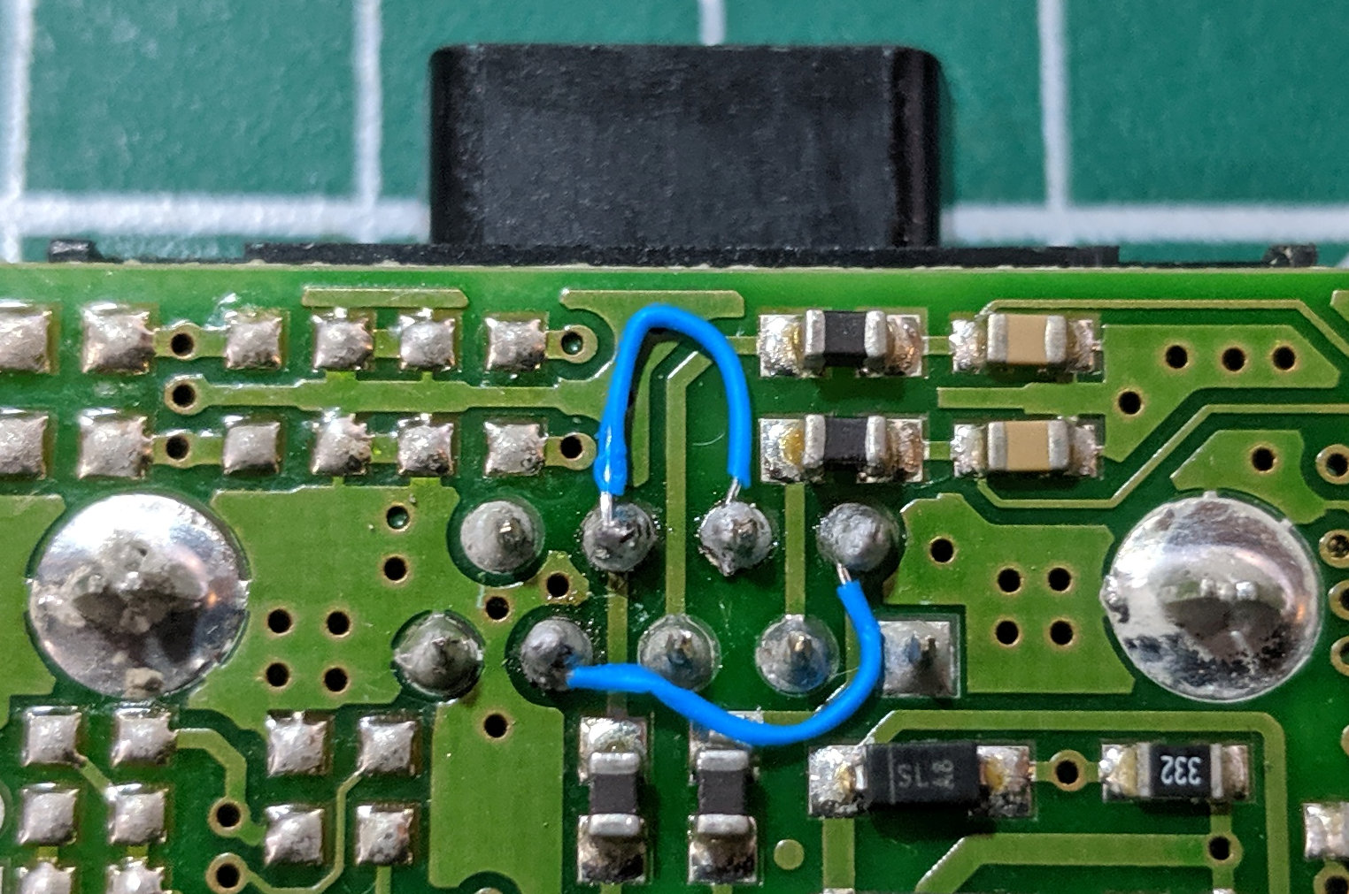
The mod is now complete
Step 5 – Re-Assembly
Follow the disassembly instructions in reverse order, be very careful not to trap or pinch any wires, especially the internal coax. The ACOM 600S will now support not only the custom cable wiring specified in the manual but also a standard straight through RS-232 cable for both computer control and remote power on.